
On line and off line Inspection Systems
Base on a standard camera, we developped a Q.C systems and implemented suitable detectors for process monitoring and TTLV.
The Quality Control module/Optical design is based on a high resolving microscopic objective. We developed some illumination strategies/Image processing algorithms for assimilation of processing results.
Clic on the image to see the video presentation of the project
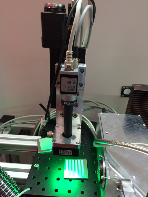
Off Line and In Line modules for In Line and Out Line Inspection
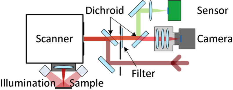
We designed an optical scanning system allowing the transmission of the visible spectrum without being disturbed by the processing wavelength of the laser. The online monitoring system attached to the scan system is used for document and analyze the texturing process. An offline quality control module was also designed to evaluate the quality of the structuring result. Both systems are used to check the textured pattern for deviations from the intended pattern.
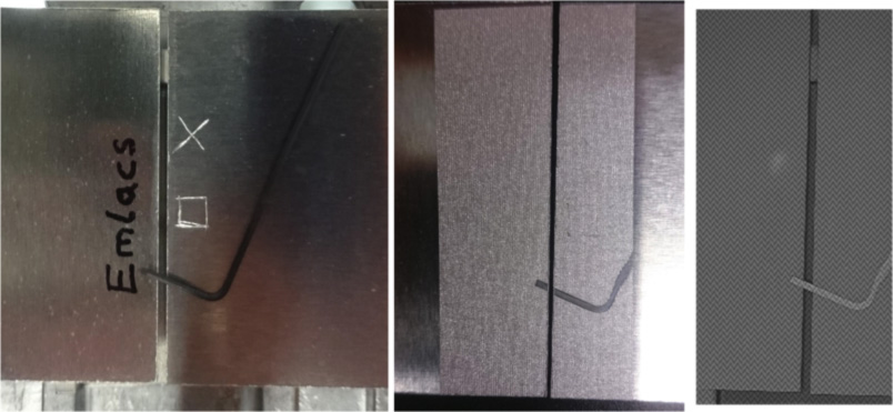
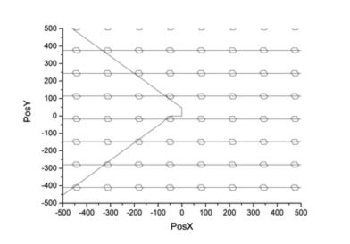
Test case for the TTLV monitoring module
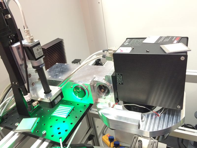
Outlook of the Quality Control module In Line
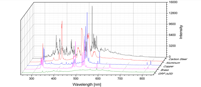
Wavelengths analysis vs material absorption and process control needs
The standard coatings of the scanning mirrors are usually only optimised for the used laser wavelength and not for process observation. In the present case of the laser wavelength of 1064nm most scanner systems do not transmit in the visible range or in the near infrared range. This prevents a successful detection of process emissions of the online monitoring system.We defined the spectral reflectivity ranges of the scanner mirrors required to monitor laser structuring based on measured emission spectra of ps texturing of selected materials. In cooperation with the scanner supplier, an appropriate mirror coating for this application was designed.
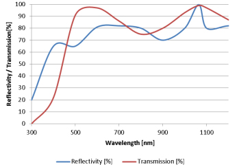
Reflectivity/transmission of the mirror coatings vs material properties
General coating Spécifications
- Laser wavelength: 1030 – 1090nm
- Maximum average power: 250W
- Maximum energy density for continuous operation: 500W/cm2
- Damage threshold (10ns pulse length, 200 pulses): >5J/cm2
- Reflectivity (45° angle of incidence)
- >99,7% @ 1030nm – 1090nm
- >65% @ 400nm – 500nm
- >99,7% @ 600nm – 800nm
- >99,7% @ 1070nm – 1600nm
Hardware eletronics and data acquisition
The sensor that monitors the prrocesd is adapted to the required and indentified spectrum. Specific electronic circuitry are used to amplify and digitize the output of that sensor and to provide the data interface for the real-time acquisition. Signal distribution electronics were designed to capture the scanner position and the sensor signals synchronously in real time. These signals have to be captured synchronously in order to correlate position and sensor signal. The data and signals from the different sources are collected by a software running on the FPGA of a programmable frame grabber. The frame grabber gives the ability to include images of a high speed camera into the data stream in the future.
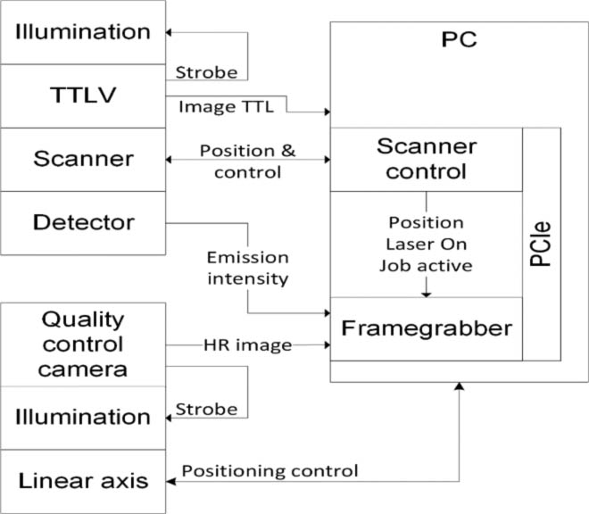
The raw data (scanner position, laser control signals and sensor signal) are stored in the HDF5 data format that is supplied by many software libraries. The recording starts and stops automatically and is controlled by the status of the scanner control card that indicates if a texturing process is running or not. The raw data can be analyzed automatically or manually offline. The analyzing result includes a process intensity image that shows the process emission intensity correlated to the scanner position. This image is independent from the texturing strategy. Furthermore the pattern of the texturing is reconstructed from the data and characteristic values are identified or calculated. These values are saved in table form in a text file. Apart from the data files, the raw data, the process intensity image and the result analysis can be visualized for further used.
User interface of the On Line QC module
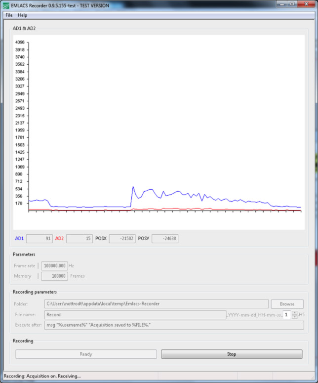
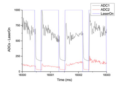
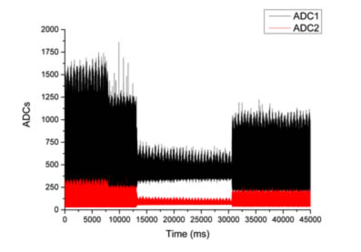
Screen ouput showing the signal intensuty coming from both sensor channel (blue and red line)
The hardware consists of a camera with microscopic lens and a LED-illumination. In additional a stepper linear stage is used for adjusting the focus of the camera. The offline monitoring system is used for visual inspection of suspicious locations of the textured pattern. For compatibility the camera is the same camera (Basler acA2500–gm14) used in the TTLV system by ILS. The following table summarizes the specification of the offline monitoring hardware.
- General Specifications
- Camera resolution : 2592 x 1944 pixel
- Magnifictaion : 2
- Pixel size on imlage : 1.1 µm
- Optical resolution : 3,9µm
- Working distance : 47mm
- Field of viewField of view : 2,851 x 2,193 mm2
- Frame per second : 14
- Travel range of Linear axis : 50 mm
- Resolution of the lminear axis : 150 nm
Type of images
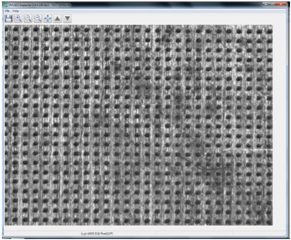
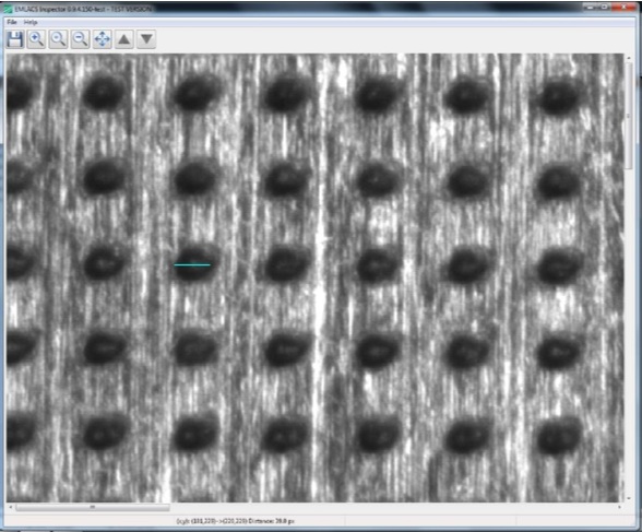
The offline quality control module can be mounted on any standard optical table with a grid of M6 threads with a grid distance of 25mm or at a vertical plate with or without linear axis. With the interface software, the user can control the camera and the linear stage. A digital zoom function supports the user analyzing smallest features. With the calibrated point-to-point distance measurement the user can analyze the size of the structured pattern. The image of the offline monitoring system can be saved for further analysis or documentation.
adidas heliopolis hotel in dubai , adidas concord ankle fur sneakers boys running Release Date Info , MysneakersShops | Women's Nike Air Jordan 1 trainers - Latest Releases , Ietp
Partners


